

1. The outstanding function is to use two LMD18200. One board can control two DC motors at the same time with better cost performance.
- Chip: lmd18200t motor driver chip
- Lmd18200t chip working voltage: DC 4.5 ~ 5.5V.
- The power supply voltage of motor drive is DC 12-35v. (Note: the motor driving voltage shall not be greater than 35V or less than 12V)
- When the power input is normal, there is led indicator.
- When the motor is in normal operation, it will be indicated by LED.
- Maximum output current 3A (instantaneous peak current 6a), maximum output power 75W.
- The input control has optocoupler isolation and strong anti-interference ability.
- It can control two DC motors.
- The positive and negative rotation of the motor can be realized.
- The motor speed can be adjusted by PWM.
- Lmd18200t chip itself can be overheated or over-current protection.
- Size of driving plate: 63mmx61mmx30mm
- Installation size: 58.5mmx55.5mm hole diameter: 3.5mm
2.
[control interface description]
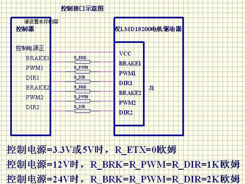
The control interface of the driver adopts the optocoupler common anode connection method to realize the isolation function, so there is no need to connect the ground of the control end on the driver, and the control loop is formed through the ground of the control end, which also avoids the interference of motor starting caused by the common ground of the control ground and the drive ground; as long as the power supply of the control end (generally + 3.3V, + 5V, + 12V, + 24V, etc.) is connected to the driver end It can be installed on the VCC of port J1.
MCU, DSP, arm, PLC, CPLD, FPGA and so on can be used in the control end. Because the power supply voltages of various controllers are inconsistent, we design the controller to support 3.3v-9v by default. If the control power supply voltage you use is greater than 9V, you need to do different resistance matching. See the following diagram for details:
Control power supply: refers to the power supply of CPU or PLC in the control system such as single chip microcomputer.
Driving power supply: refers to the power supply used by the motor.
Interface Description:
J1: interface between driver and control terminal
VCC --- connected to control system power supply
Brake1 --- motor 1 brake control input, high level brake, low level enable.
Dir1 --- motor 1 direction control input, high level forward rotation, low level reverse.
Pwm1 --- motor 1 speed control input, high-level motor runs at full speed, low-level motor stops. When PWM output pulse width modulation signal, the motor can adjust speed.
Brake2 --- motor 2 brake control input, high level brake, low level enable.
Dir2 --- motor 2 direction control input, high level forward rotation, low level reverse.
Pwm2 --- motor 2 speed control input, high-level motor runs at full speed, low-level motor stops. When PWM output pulse width modulation signal, the motor can adjust speed.
J2: motor drive power input interface
The range is DC 12v-35v. V + is positive, GND is grounded, pay attention not to reverse the polarity of power supply.
J3: output motor 1 interface
Motor output: J2